
Originally I used to unclip the bridle from the boat and leave it hanging on the halyard, but it was a bit of a wet job refitting the bow end before lifting and I realised there was no point in removing it. The three legs are spliced together at a stainless ring which the halyard clips to. The bridle has a small carbine hook on the end of each leg the bow one hooks onto the painter ring, and the stern ones to thin Dyneema (because it’s what I had to hand any cord would do) grommets spliced through small holes near the top of the transom. Not to mention the engine would be in the way. You’d end up lowering the dinghy down sideways, it‘s never going to balance. I use a long three-legged bridle, and I can’t see a two-legged one being a good idea. I lift it with the outboard fitted, which I find much easier and safer (for the engine) than trying to lift it separately and clamp it on in the water. Hence my thoughts about junking it.heavy, hangs below the bridge deck, and possibly many more maintenance issues.īut, for now I will rewind the motor if is reasonable cost.I do exactly this, using the spinnaker halyard to lift the dinghy to and from the foredeck where I inflate and deflate it. go back inside turn breaker off.and reverse upon return. Cannot just drive away and park/lift upon return. This negates the great usefulness of the system. The quandary is the switches can never be trusted, so the main breaker needs to be off when not in use. I intend to make my own from a waterproof toggle switch imbedded in a PVC pipe/handle filled with silicone. I am done paying $100's for non-waterproof waterproof switches. I disconnected the motor and used "up" solenoid while pumping.

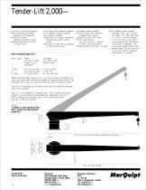
ILIFT TENDER LIFT MANUAL
It has a manual lever that works pretty well. I have already upgraded the controllers to have control breakers for the direction solenoids, a bypass for the remote, and another up/down switch at the unit. And then a bypass switch for the limit switch. Switch would then be located in drier area. I will look at having a plastic rod (batten/pvc tube) mounted at bottom of ram attachment point to near top of ram attachment point to engage a limit switch. The entire assembly is below the bridge deck, and subjected to wave action. Most mechanical systems have them.īut, we are back to switches in the marine environment. Not sure what the original remote fobs were( marine or garage door) but the three I have purchased are all name brand windless controllers, and fail due to water ingress. I have been thru 4 different remotes (wired and wireless) in 4 years. It needs limit switches - but does not have them. Even if you continued to press the up or down button on a remote (if that's how it works) and tried to make the lift over-travel and get to a hard, mechanical stop, a properly designed system would have "idiot proof" protection to keep it from trying to keep going. Having such a mechanism is pretty typical in hydraulic systems. Perhaps the motor continuing to run is just a symptom of the real problem - either there's a failed limit switch or some other failed component present that makes up a "fail safe" ultimate protection mechanism. Thinking about this some more, one could expect that there should be limit switches in the lift travel mechanism that activate relays to interrupt power to the motor to specifically prevent what you described happened.


 0 kommentar(er)
